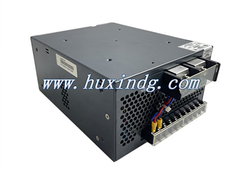
Common Faults and Maintenance of Generator Set Electrical Control System
The fault diagnosis and maintenance of the electrical control system of the generator set is the key to ensuring the stable operation of the unit. The following is a systematic summary of common fault types, cause analysis and maintenance methods:
I. Classification and Manifestations of Common Faults
Startup failure
Phenomenon: No response when starting, difficult to start, and the engine stalls immediately after starting.
Possible reasons:
The battery voltage is insufficient or the wiring is loose.
The starter motor/relay is faulty.
The fuel solenoid valve is not powered on or stuck.
The ECU (Electrical Control Unit) did not output the start signal.
Unstable operation
Phenomena: Fluctuation in rotational speed, insufficient power, sudden shutdown.
Possible reasons:
Sensor failure (rotational speed sensor, temperature sensor, pressure sensor, etc.).
Problems with the fuel injection system (clogged fuel injectors, faulty high-pressure fuel pumps).
Intake system leakage or turbocharging failure.
ECU program error or communication interruption.
Alarm and protection shutdown
Phenomenon: The fault light is on, showing overvoltage/undervoltage, high temperature, low oil pressure, etc.
Possible reasons:
Abnormal sensor signals (such as failure of the oil pressure sensor).
Cooling/lubrication system failure (water pump, thermostat, oil pump).
Overload or short circuit causes the protection to act.
Communication failure
Phenomenon: No display on the monitoring screen, data not updated, remote control failed.
Possible reasons:
The CAN bus communication line is short-circuited/open-circuited.
The controller (ECU) or display module is damaged.
The software versions are incompatible.
Ii. Fault Diagnosis Steps
Preliminary inspection
Check the power supply (battery voltage, fuse, grounding wire).
Observe the fault code (read the historical alarm records through the panel).
Check whether the fuel and gas lines are unobstructed (fuel filter, air filter).
Sensor and actuator testing
Use a multimeter to measure the resistance/voltage of sensors (such as crankshaft position sensors and camshaft sensors).

Check the actuator operation (such as whether the fuel injector solenoid valve is energized).
ECU Diagnosis
Connect the dedicated diagnostic instrument to read the ECU fault code (such as Bosch EDC, Delphi system).
Check the power supply and output signals of the ECU (such as the width of the fuel injection pulse).
Load and line inspection
Simulate load testing to eliminate faults caused by sudden load changes.
Check whether the plugs of the wiring harness are oxidized or loose (with a focus on inspecting the vibrating parts of the wiring).
Iii. Typical Fault Repair Cases
Case 1: The unit fails to start
Phenomenon: No fuel supply when starting up.
Handling:
The power supply of the fuel solenoid valve was inspected and it was found that the relay contacts were eroded.
It returned to normal after replacing the relay.
Case 2: Sudden power drop during operation
Phenomenon: Accompanied by black smoke coming out of the exhaust.
Handling:
The diagnostic instrument shows "The signal of the intake pressure sensor exceeds the limit".
The fault disappeared after cleaning the sensor pipeline and replacing the sensor.
Case 3: Communication interruption
Phenomenon: The monitoring screen shows "Communication timeout".
Handling:
Check the terminal resistance of the CAN bus (normal value 120Ω) and find that one end of the resistance is missing.
Communication was restored after the damaged terminal resistor was replaced.
Iv. Preventive Maintenance Suggestions
Regular maintenance
Clean or replace the sensors (such as oxygen sensors, oil pressure sensors).
Update the ECU software version (for the upgrade patches released by the manufacturer).
Environmental Management
Moisture-proof and dust-proof (especially for coastal or high-dust environments).
Avoid long-term operation in high-temperature environments (heat dissipation should be enhanced when the temperature exceeds 50℃).
Spare parts reserve
Always keep key sensors, relays, fuses and other vulnerable parts on hand.
V. Precautions
Safe operation: Before maintenance, be sure to disconnect the negative terminal of the battery to prevent short circuits.
Professional tools: Give priority to using original factory diagnostic equipment (such as Cummins INSITE, Volvo PTT).
Parameter recording: Key data (such as fuel injection timing and idle speed) are recorded before and after maintenance for easy comparison and analysis.
Through systematic fault detection and preventive maintenance, the failure rate of the electrical control system of the generator set can be significantly reduced. For complex issues (such as internal ECU malfunctions), it is recommended to contact a professional service provider for handling.


